sheet metal drawing solidworks
If a message appears that says sheet metal features cannot be mirrored individually click OK. Drawings of sheet metal parts can also contain views of the bent sheet metal part.

Solidworks Exercise Files Training Files Mechanical Drawings Sheet Metal Drawing Solidworks Sheet Metal
Solidworks Tutorials SHEET_METAL_DRAWINGS.

. All sheet metal parts have a fixed face. SolidWorks for Sheetmetal 1. It might even require some significant user input for proper documentation.
To do this we simply need to right-click any tab on the. 1 Sketches created in the folded state can have an equivalent transformed sketch in the Flat Pattern state. Orient your sketch to an Isometric view.
We will focus on the flange method where a sheet metal part is created in the formed state using specialized sheet metal features. In an existing sheet metal part click Mirror on the Features toolbar or click Insert PatternMirror Mirror. From the View Palette drag.
How to add Sheet Metal Properties to Drawings. SOLIDWORKS Sheet Metal Properties can be added to Drawings using a predefined annotation or selectively using standard annotation property mapping syntax. SOLIDWORKS DESIGN SOLIDWORKS DRAWINGS SOLIDWORK SHEET METAL PARTIn this we learn solidwork sheet metal part modelYou Can Support our Channel for more tut.
How to Use SolidWorks Edge Flange SolidWorks Sheet Metal Tutorial 2. The secret is the annotation MUST be attached to the Flat Pattern view. Provide feedback on this topic.
To begin we first want to turn on the Sheet Metal tab on the CommandManager. When cuts are made into the flat pattern of a rolled sheet metal cylinder or semi-cylinder it is not always easy to extract model dimension data in a SOLIDWORKS drawing. To mirror a body in a sheet metal part.
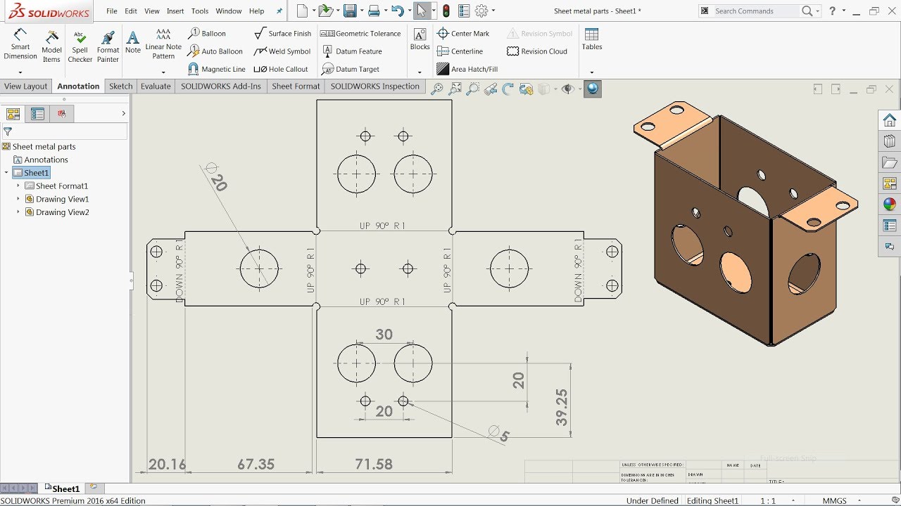
Drawings of Sheet Metal Parts. We can use these features to create sheet metal designs with several different methods. SolidWorks Sheet Metal Drawing Tutorial Bend Line Flat Pattern Unfolded Bend Table Punch Table.
SHEET_METAL_DRAWINGS No matter what kind of information you provide CEYLON_CAD_SERVICES can support you with service and solutions. Start a new inch part right click on any toolbar and check the Sheet Metal tool for the Sheetmetal toolbar to be available. Use the Convert to Sheet Metal feature.
You can create dxf files of sheet metal flat patterns without creating a drawing. Such as complete drawings released or rough sketch pop into. Sheet metal parts can have sketches in the Folded and the Flat Pattern states Fig.
Right-click inside the border of a drawings Flat Pattern view and then select. When using the Insert Bends or Convert to Sheet Metal features apply the features as early. While some people may say the answer is simple there are several ways to get the Bend Lines to show or not show in your drawing.
When you create a drawing of your sheet metal part a flat pattern is automatically created. When the Flat-Pattern drawing view of a SOLIDWORKS sheet metal part displays the part in the bent configuration this often indicates an issue with the suppression state of the Flat-Pattern feature in the part file. This tutorial show how to create production drawing for.
You can create dxf files of sheet metal flat patterns without creating a drawing. Create a new Sketch on the front plane. Select a format or click OK to use the default format.
By Tutorial45 April 6 2020. Use the Insert Bends feature. With sheet metal designs when you have more than one body SOLIDWORKS will create separate flat patterns and cut lists on the FeatureManager Design Tree.
In this tutorial video we will learn how to sketch sheet metal drawings in Solidworks with the help of sheet metal toolsPlease subscribe our channel for mor. Sheet metal is metal formed by an industrial process into thin flat pieces. Sketch a 600 inch square rectangle that is centered on the UCS origin.
Drawings of sheet metal parts can also contain views of the bent sheet metal part. But when it comes time to create a 2D drawing if you have a multibody sheet metal part you will not see a flat pattern view by default when adding a model view onto the drawing. Sheet metal is one of the fundamental forms used in metalworking and it can be c.
Select the fold feature in the sheet metal tabSelect the same face as when you unfolded your part this is good practice as you might be working with many parts which will need to fit back together once refoldedSelect collect all bendsSelect the green tick You now have your realistic sheet metal without any wonky cuts ready for assembly. Without proper design intent detailing the flat pattern positions may not work. When designing sheet metal parts the order preference for use of feature tools are as follows.
Click Make Drawing from PartAssembly Standard toolbar and click OK to open the drawing sheet. Here is a quick Solidworks sheet metal tutorial. How to Show Sheet Metal Bend Lines in a SOLIDWORKS Drawing A customer had recently called in looking for a way to show his Bend Lines on the drawing of his sheet metal parts.
The sheet metal tool allows you to quickly create sheet metal part designs using a simple design process all helping to save time and development costs. Lets see how this works. Open the sheet metal part for which you want to add a drawing.
SOLIDWORKS Flat-Pattern Not Working in Drawing View. In the base flange section you seen the very first step to make sheet metal design in SolidWorks CAD software. Search Drawings of Sheet Metal Parts in the SOLIDWORKS Knowledge Base.
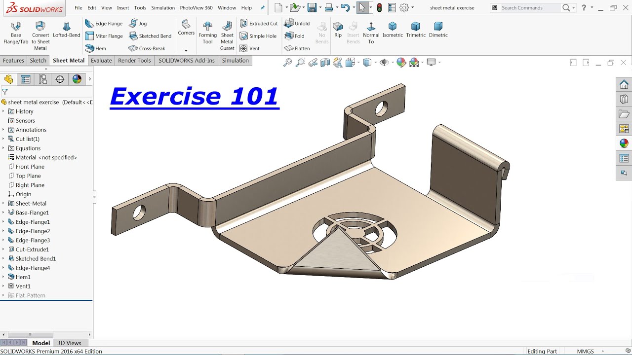
Use sheet metal features such as base-flanges edge-flanges miter flanges etc. In the PropertyManager select a plane of symmetry or a planar face as the Mirror FacePlane. The picture below shows the Reference Configuration for the drawing view selected is DefaultSM.
The fixed face is the one that remains in the same position when unsuppressing the Flat Pattern. The Edge Flange feature helps to add flanges to selected edge or more edges. The condition of application of Edge flange is that the Edges should be linear.
To show the flat pattern.

Using Solidworks Sheet Metal Functionality Create A B Size Drawing Sheet Metal Drawing Technical Drawing Mechanical Engineering Design

Advanced Sheet Metal Exercise In Solidworks Youtube Solidworks Tutorial Sheet Metal Drawing Solidworks

Pin On Solidworks Sheet Metal

Pin On Solidworks

Solidworks Sheet Metal 2d To 3d Sheet Metal Drawing Solidworks Tutorial Sheet Metal
Solidworks Tutorial Sheet Metal Drawings Youtube Sheet Metal Drawing Solidworks Tutorial Solidworks

Pin On Solidworks Sheet Metal

Solidworks Tutorial For Beginners Learn How To Design A Part 07 Youtube Solidworks Solidworks Tutorial Sheet Metal

Pin On Solidworks

Sheet Metal Practice Drawing Sheet Metal Drawing Sheet Metal Drawing Practice

Pin On Solidworks

Pin On Solidworks Sheet Metal

Pin On Solidworks Sheet Metal

Solidworks Sheet Metal Tutorial Electrical Enclosure Youtube Sheet Metal Sheet Metal Furniture Design Design Weldi Sheet Metal Drawing Sheet Metal Solidworks

Autodesk Inventor Sheet Metal Tutorial Basics Youtube Sheet Metal Drawing Autodesk Inventor Solidworks Tutorial
Pin On Solidworks
Pin On Solidworks

Pin On Solid Draw

Autodesk Inventor Sheet Metal Drawing Tutorial Basics Youtube Sheet Metal Drawing Autodesk Inventor Drawing Tutorial